Ok, the documentation is there. It’s available in English too. I still get questions about connecting the reed switches. The diode matrix I made for my test track was a quick hack with available materials. After evaluation this design was not very suited for a publication. This is a second attempt to design a cheaper alternative for connecting the reed switches.
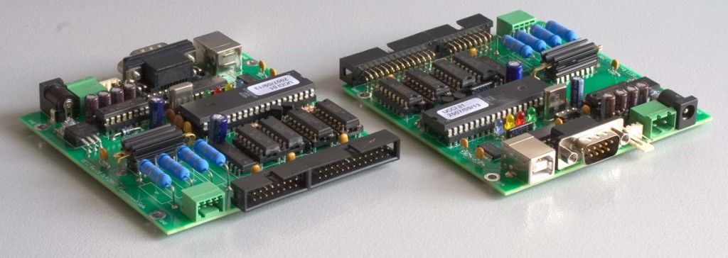
About the UCCI. The black multi pin connectors you may recognize as a floppy or hard disk cable connector are used on the UCCI to connect the reed switches. You cannot connect the switches directly to the controler. They are multiplexed. Now for some of us this is a somewhat mysterious technique. I will not try to explain this, just google for the numerous explanations. Just think of it as a way to connect lots of reed switches with as little cables as possible.
Leon kindly designed a diode matrix for us. You can order it from his website. Before this was available I designed a prototype for Railz Miniworld. Combined with the test track thingy I now present a do-it-yourself version of the SWDEC.
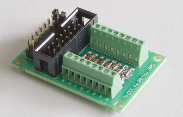
With two flat cables you can connect 128 reed switches. It does not matter which connector you use first. The flat cables can me about 10 meters each.
It is advised to use them as described in the next picture:
All the connectors are female connectors.
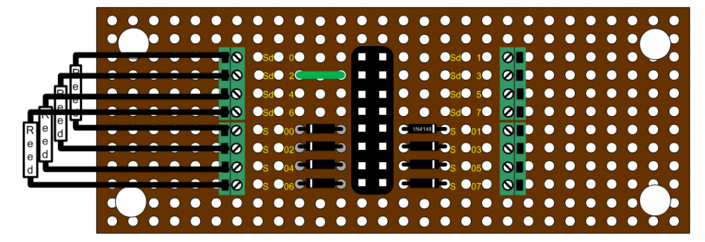
The reed switches and diodes must be connected as shown in the next picture. Each reed switch is connected to a single Sxx channel. the return connection is one of the SDx channels.
For every connector you will have to choose a different SD channel.
The board to use is called strip board or Veroboard.
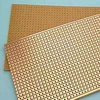
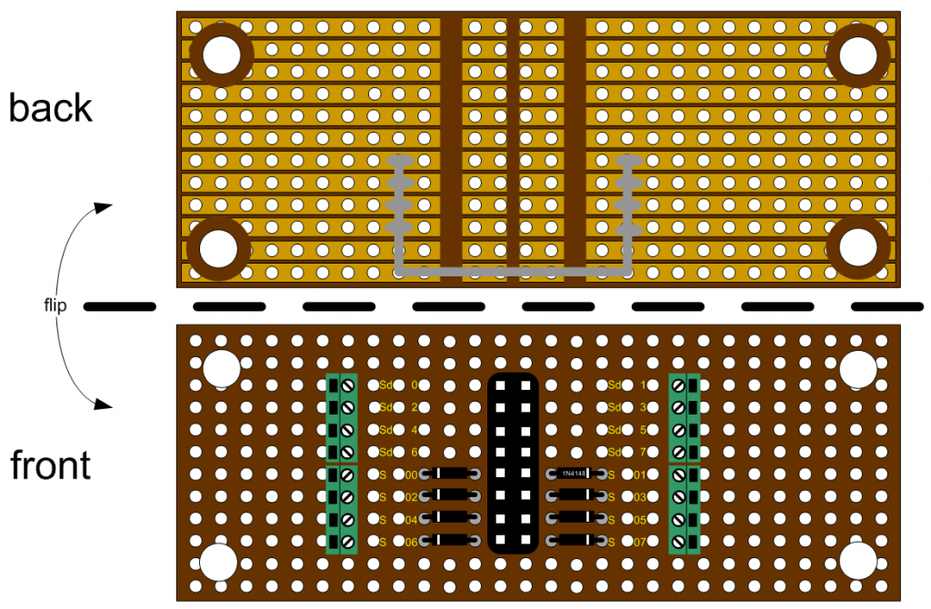
First the back side. In the middle you will have to remove three stripes of copper. On the corners you will need some holes. Remove the copper around the hole to prevent a short circuit here.
The grey line is a extra connection you will have to solder on the copper. It connects the 8 bottom stripes.
On the front side you place the connector. This is a print header. Buy these in long strips and break or cut off 16 pins.
Eight diodes of the type 1N414B. These are the cheapest you can find. The indicator ring is on the outside pointing away from the middle 16 pin connector.
The green connectors are very expensive.
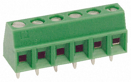
Of course you can decide to skip these and solder your wires directly to the copper on the back.
The green connection is unique for every matrix you make. It chooses the return channel. In the example SD2 is chosen. If you look at the back you can see that this connection touches the wire on the back side indicated with grey in the first picture.
The reed switches are connected as shown. One leg on the SDx channel, the other via the diode to the Sxx channels.
That’s it. Don’t forget to change the green connection for every board you make. On every flat cable you can connect 8 of these boards.
Good luck!
Please send me some pictures of your results.
Hans.

